Learn how AND, OR, and NOT gates work in digital electronics with practical examples and interactive simulations. Perfect for beginners and students.
What Are Logic Gates in Digital Electronics?
Logic gates are the fundamental building blocks of digital circuits that process binary inputs (1s and 0s) to create outputs based on specific rules. Whether you're studying computer science, electrical engineering, or just starting with digital electronics, understanding logic gates is essential for building everything from simple circuits to complex microprocessors.
The Three Basic Logic Gates Every Electronics Engineer Should Know
AND Gate: Complete Tutorial & Truth Table
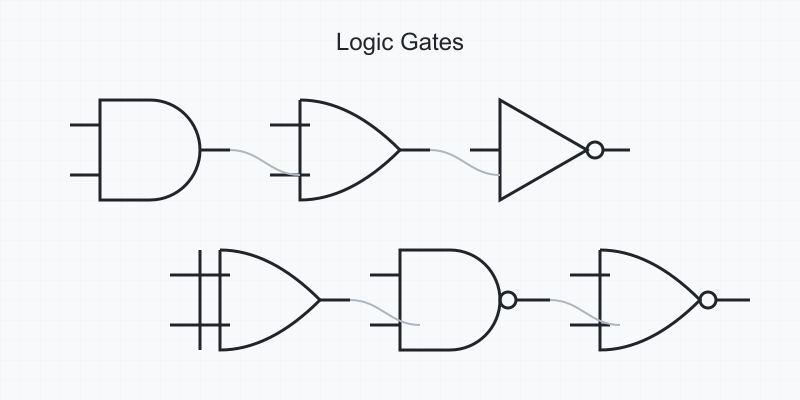
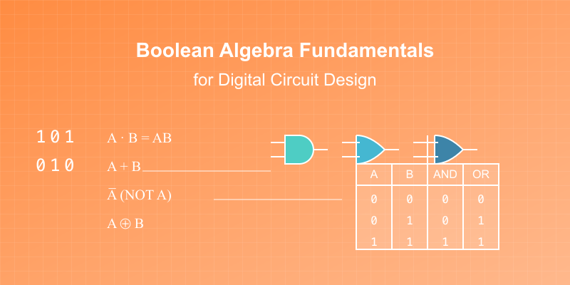
An AND gate outputs 1 (HIGH) only when all inputs are 1. It's the foundation of digital multiplication and conditional operations in computer processors. Here's what you need to know:
Symbol:

Truth Table:
A · B = 1 only when both A AND B are 1
Truth Table:
A B | Output
0 0 | 0
0 1 | 0
1 0 | 0
1 1 | 1
Interactive AND Gate Simulation - Try it Now
OR Gate: Step-by-Step Explanation
The OR gate outputs 1 when any input is 1, making it crucial for detecting multiple conditions in digital systems. Key points:
Symbol:

Truth Table:
A + B = 1 when either A OR B (or both) are 1
Truth Table:
A B | Output
0 0 | 0
0 1 | 1
1 0 | 1
1 1 | 1
Interactive OR Gate Simulation - Try it Now
NOT Gate (Inverter): Comprehensive Guide
The NOT gate (inverter) reverses its input, making it essential for creating complementary signals in digital circuits:
Symbol:

Truth Table:
A' = opposite of A
Truth Table:
A | Output
0 | 1
1 | 0
Interactive NOT Gate Demonstration - Try it Now
Common Logic Gate Applications in Electronics
1. Digital Circuit Design Examples
- Simple burglar alarm system
- Basic calculator circuits
- LED control systems
- Digital lock mechanisms
2. Computer Hardware Applications
- Memory storage elements
- Arithmetic logic units (ALU)
- Clock signal generation
- Input/output control
Interactive Logic Gate Circuit Builder
Try building these basic circuits in our interactive simulator:
Scratchboard - Online Embedded Circuit Simulator (Design Your First Digital Circuit)
Example projects to try:
- Two-input door alarm system
- Simple combination lock
- Basic traffic light controller
- LED sequence generator
Logic Gates Practice Problems and Solutions
Test your understanding with these practical exercises:
- Design a circuit that lights an LED when both switches are ON
- Create a burglar alarm that activates when any sensor is triggered
- Build a simple voting system using AND and OR gates
Try These Exercises in Our Interactive Simulator
Start Building Your Own Digital Circuits
Ready to experiment with logic gates? Create your free account at Scratchboard and access our full suite of digital design tools. Our browser-based circuit simulator makes it easy to:
- Design and test digital circuits instantly
- Simulate real-world electronic components
- Share your projects with others
- Learn through interactive tutorials
Ready to master Logic Gates? Sign up for Scratchboard and access our complete suite of interactive digital design tools.


