
Learn the key differences between combinational and sequential circuits, their applications, and how to design them. Perfect for students, hobbyists, and aspiring digital designers.
Understanding Digital Circuits: The Basics
Before diving into the differences, let's understand what makes digital circuits the foundation of modern computing. All digital circuits fall into two main categories: combinational and sequential. Each has distinct characteristics that make them suitable for different applications.
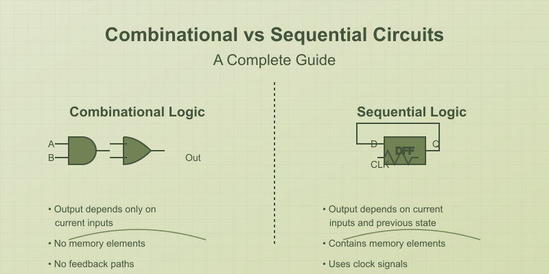
Combinational Circuits
What Makes a Circuit Combinational?
Combinational circuits are digital circuits where:
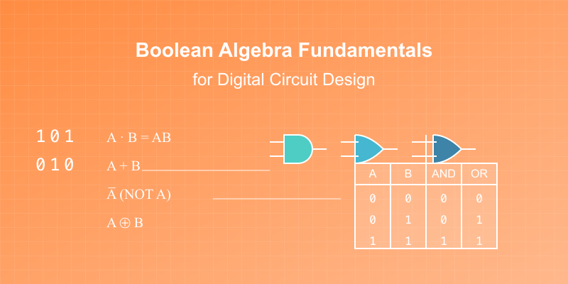
- Outputs depend only on current inputs
- No memory elements
- No feedback paths
- No dependence on past states
Think of them as "instantaneous" decision-makers - like a calculator that gives you an answer based solely on the buttons you're currently pressing.
Common Combinational Circuit Examples
- Multiplexers (MUX)
A multiplexer, often abbreviated as MUX, is a fundamental digital circuit component that selects one output from multiple input signals based on control signals (also called select lines). Think of it as a digitally controlled switch.
output = select ? input1 : input0;
- Full Adders
A Full Adder is a digital circuit that adds three single bits (A, B, and Carry-in) to produce a Sum and Carry-out.
sum = A ^ B ^ Cin;
carry = (A & B) | (Cin & (A | B));
- Demultiplexer
A demultiplexer (DEMUX) distributes one input to multiple outputs based on select lines.
// 1-to-4 demux
output[0] = enable & !select[1] & !select[0];
output[1] = enable & !select[1] & select[0];
output[2] = enable & select[1] & !select[0];
output[3] = enable & select[1] & select[0];
Sequential Circuits
What Defines a Sequential Circuit?
Sequential circuits include:
- Memory elements (flip-flops, latches)
- Outputs depend on both current inputs AND previous states
- Timing elements (clock signals)
- Feedback paths
Think of them as circuits with "memory" - like a traffic light that needs to remember its current state to determine its next state.
Basic Sequential Elements
- D Flip-Flop
D Flip-Flop: Edge-triggered storage element that captures input D on clock edge.
always @(posedge clock)
    Q <= D;
- Counter
A 4-bit counter is a sequential digital circuit that cycles through a sequence of binary numbers (0000 to 1111) on each clock pulse. It can count up to 15 (2^4 - 1) before rolling over to 0. The counter uses four D flip-flops to store its current value and incrementing logic to compute the next state. Common features include:
always @(posedge clock)
    count <= count + 1;
Key Differences: Side-by-Side Comparison
Timing Behavior
- Combinational: Immediate output changes
- Sequential: Output changes synchronized with clock
Memory
- Combinational: No memory storage
- Sequential: Stores previous states
Feedback
- Combinational: No feedback loops
- Sequential: Uses feedback for state maintenance
Design Principles and Considerations
Combinational Circuit Design
- Gather requirements
- Create truth table
- Derive Boolean equations
- Simplify using Boolean algebra
- Implement with gates
Example: 2-bit Comparator
equal = (A[1] == B[1]) && (A[0] == B[0]);
greater = (A[1] > B[1]) || ((A[1] == B[1]) && (A[0] > B[0]));
Sequential Circuit Design
- Define states
- Create state diagram
- Choose flip-flop type
- Write state transitions
- Implement with flip-flops and combinational logic
Example: Simple Traffic Light Controller
case(current_state)
    RED: next_state = GREEN;
    GREEN: next_state = YELLOW;
    YELLOW: next_state = RED;
endcase
Common Applications
Combinational Circuits
- Arithmetic Logic Units (ALU)
- Code converters
- Multiplexers/Demultiplexers
- Priority encoders
Sequential Circuits
- Registers
- Counters
- Memory units
- State machines
- Control units
Try It Yourself in Scratchboard
Combinational Circuit Exercise
- Design a 4-bit priority encoder
Sequential Circuit Exercise
- Create a 3-bit binary counter
Design Tips and Best Practices
- Combinational Circuits
- Minimize propagation delay
- Avoid unintended feedback
- Consider fan-out limitations
- Sequential Circuits
- Ensure proper timing
- Handle reset conditions
- Avoid race conditions
- Consider clock skew
Debug Common Issues
Combinational Circuit Issues
- Glitches
- Multiple signal paths
- Timing violations
Sequential Circuit Issues
- Setup/Hold violations
- Clock skew problems
- Race conditions
- Metastability
Next Steps in Digital Design
Ready to advance your digital design skills?
- Start with basic combinational circuits
- Move to simple sequential elements
- Combine both in larger projects
- Try advanced state machines
Ready to experiment with both types of circuits? Create your free Scratchboard account and access our interactive circuit simulator.


)